3COM:
Fixing a noisy Switch
Turns out that one of the routers at the lab is *extremely* noisy when powered. So they gave it to me to fix! Goody!
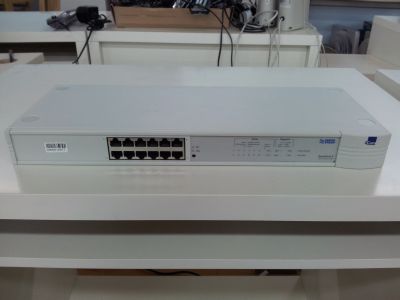
The unit is an older 3COM unit (SuperStack II Port Switch Hub).
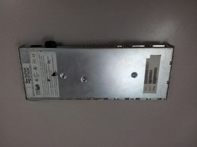
Here's a shot of the bottom of the unit
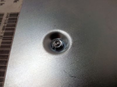
Upon inspection, it appears that the unit is held together with just a couple of TORX screws located at the bottom of the unit.
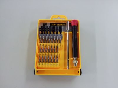
Luckily, just last week I gave myself a little XMAS present...tools!
One of my little purchases was a complete micro-screwdriver kit, which handily included a TORX set, which had already turned in to be very handy in a couple of other situations. Long story short, getting the screws out of the 3COM was a doodle. Easy! I thought that once the TORX screws were removed it would be easy to get the plastic cover off....but no!
Turns out that getting the plastic casing off of a 3COM chassis is a complete pain in the neck!
Eventually, I got the darn thing off by *carefully* levering the little clips away from the chassis and *slowly* sliding the casing up.
With the casing removed, getting the fan out was simple. Just unplug it from the motherboard and gently wiggle it out of place.
Next, a quick trip to Ap Liu Gai to find a replacement fan and then a quick re-assembly
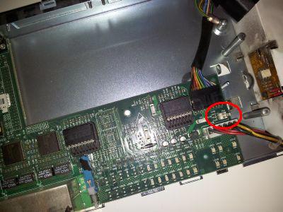
A shot of the main board and the connector for the fan highlighted
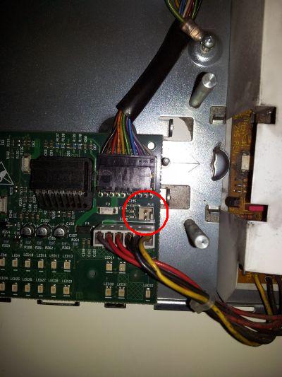
Detailed shot of the fan connector. Note polarity of connector. One way
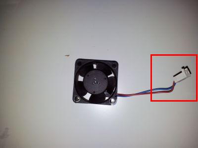
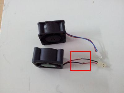
The new fan. Lovely but can you see what's wrong with it?
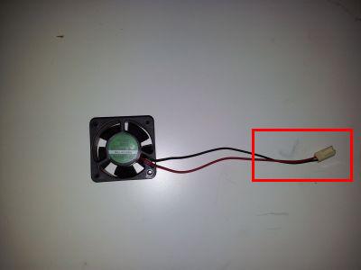
To refresh your memory, here is a shot of the old fan...
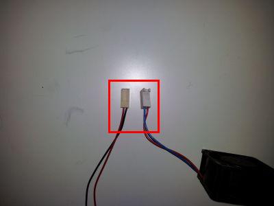
Yup...the connectors are the WRONG WAY around
Alright, inverting the leads is not normally recommended...but...
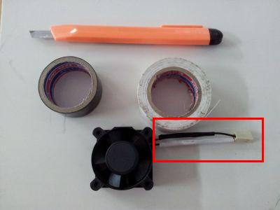
Wires re-badged to prevent any misunderstandings in the future....
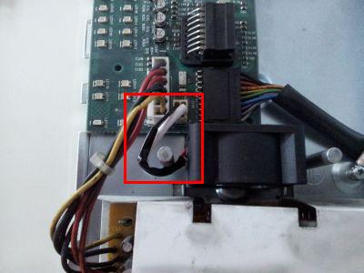
The new fan installed and 3COM is ready for the re-assembly!
SOLVED
